Introduction
A metal insert can strengthen a molded component, provide an electrical path, or create a durable fastening point. But once that insert is placed inside an injection mold, its design affects far more than the metal itself. The insert must stay accurately positioned while molten resin enters the cavity. Plastic must flow around it without leaving weak areas, trapped air, or incomplete coverage. Retention features must resist the loads the finished component will experience, while critical dimensions still need to remain within specification after molding. That is why successful metal insert molding begins before the molding cycle starts. Geometry, locating features, resin flow paths, wall thickness, material choice, and end-use requirements all need to work together. For design engineers, the main focus is on whether metal insert design sufficiently supports reliable molding, efficient assembly, and long-term part performance.
Metal Insert Molding and Why Insert Design is Critical
Problems in insert-molded parts often begin before the injection of resin. If the metal insert is difficult to locate, poorly supported, or shaped without regard for plastic flow, the molding process can become unstable. As a result, the insert may shift under injection pressure, create inconsistent wall thickness, trap air, or leave areas where the resin does not fully surround the metal. Consequently, there could be incomplete encapsulation, dimensional variation, cracked plastic around the insert, or weak retention in the finished part.
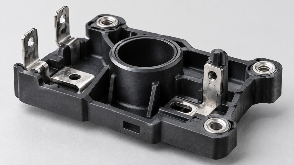
Good insert design reduces these risks by making the metal part compatible with the mold from the start. Locating features help position it consistently. Openings and formed geometry can give the resin a controlled path through or around the insert. Also, adequate spacing allows the plastic to build a strong section around critical areas.
What this means for manufacturers is that the insert should be designed as part of the molding system, not as a separate metal component inserted into a plastic part.
How Insert Geometry Affects Plastic Flow Around the Metal
Once injection begins, molten resin has to move around the insert, fill the cavity, and reconnect without creating weak or incomplete areas. The shape of the metal insert can either support that flow or disrupt it. Features such as broad flat surfaces, abrupt changes in section, and poorly placed obstructions often divide the resin flow and increase the chance of weld lines, hesitation, or trapped air. By contrast, smoother transitions, appropriate clearances, and well-planned openings can give the resin a more direct path through the cavity.
This is especially important with stamped inserts that contain bends, tabs, holes, or channels. These features can be useful for retention, but it is necessary to evaluate their effects on resin movement. Gate location matters too. If the melt reaches the insert from an unfavorable direction, the flow may split unevenly or place unnecessary pressure on one side of the metal.
The best insert geometry helps the resin fill predictably, surround the metal where necessary, and form a stable connection without creating new molding problems.
How Do You Keep a Metal Insert from Moving During Injection?
Maintaining a stable insert position is critical from mold loading through resin injection. If the metal shifts, tilts, or lifts even slightly, the finished part may develop uneven plastic coverage, dimensional error, flash, or misaligned functional features. This makes locating and support features critical.
A well-designed insert should seat positively in the mold so its position is repeatable from cycle to cycle. Features such as shoulders, holes, tabs, formed stops, or dedicated locating surfaces can help the tooling control orientation and prevent unwanted movement. The insert must also withstand the force of incoming resin. Gate direction, injection pressure, and the amount of unsupported metal all influence the extent of insert loading during filling. It is important to note that thin or flexible stamped sections may require additional support to avoid deflection.
This is one reason vertical insert molding can be advantageous for certain applications. Gravity can assist with insert loading and positioning before the mold closes, while tooling features maintain final location during injection.
Which Retention Features Work Best in Insert Molded Parts
Once the plastic cools, the insert should be locked in place under the loads the finished component will experience. That requires more than surface contact between the metal and plastic. Different retention features resist different types of movement:
- Holes and slots allow resin to flow through the insert and form a mechanical lock on both sides.
- Grooves and undercuts help resist axial pull-out by giving the plastic a feature to grip.
- Knurled surfaces increase resistance to rotation and movement along the insert surface.
- Flanges and shoulders distribute load and help prevent the insert from pushing through the surrounding plastic.
- Formed tabs or embossed features can add mechanical engagement without requiring extensive secondary machining.
The right feature depends on the expected load. A part exposed mainly to torque needs a different retention strategy than one designed to resist pull-out, impact, or repeated assembly forces. Good retention design starts by identifying the likely failure mode and engineering the insert around it.
Why Integrating Metal Stamping and Insert Molding Reduces Design Risk
When metal inserts and plastic molding are developed by separate suppliers, design decisions can become disconnected. A stamping change that seems minor may affect how the insert locates in the mold. It may also affect, how resin flows around the mold or how the finished part meets dimensional requirements.
Integrating both processes creates a more direct engineering loop. The stamping team can design features with molding in mind, while the molding team can provide feedback on insert positioning, flow paths, retention geometry, and critical tolerances. This makes it easier to refine the insert before tooling and production are fully committed.
It can also simplify quality control. If a dimensional or molding issue appears, engineers can evaluate the metal insert and molded component together rather than tracing the problem across multiple suppliers. For OEMs, that coordination can mean fewer handoffs, faster problem solving, and a better chance of getting the insert and plastic geometry right from the start.
ITD Precision’s Integrated Approach to Metal Insert Molding
ITD Precision brings metal stamping and insert molding together within one manufacturing operation. Thus, giving OEM teams a more connected path from insert design to finished molded component. Our insert molding capabilities include vertical insert molding machines designed for applications that require accurate insert placement, repeatable loading, and engineering-grade resins. Its current equipment profile lists 70-ton and 200/280-ton vertical insert molding machines with rotary-table configurations for production flexibility.
Because ITD also supports in-house metal stamping, tool and die, heat treating, e-coating, and light assembly, insert features can be developed with both the stamping and molding processes in mind. That helps reduce the disconnect that can occur when the metal insert and plastic overmolding are engineered by separate suppliers. This is advantageous for OEM engineers, providing greater coordination around insert geometry, locating features, tolerances, resin flow, retention requirements, and production repeatability.
Are you developing a stamped metal insert for an insert-molded component? Contact us to review your part design, material requirements, production volume, and molding objectives.